|
Queensland Department of Transport and Main Roads introduced the safety certificate in November 1999 to replace the old roadworthy certificate or RWC, and it became
mandatory to obtain and display a current safety certificate on any registered motorcycle from the moment it's offered for sale.
The only times it's not required to display current safety certificate on a motorcycle for sale is when the motorcycle's either unregistered or is traded to or
between licensed motor dealers.
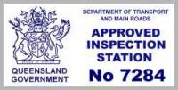
Queensland Department of Transport and Main Roads safety certificates can only be issued by Approved Inspection Stations (AIS), being service stations, garages or
workshops approved by Queensland Department of Transport and Main Roads to conduct inspections.
For private motorcycle sellers, Queensland Department of Transport and Main Roads safety certificates must be issued in the two months or 2000 kilometres prior to
sale, whichever comes first.
You are required to display a safety certificate in a conspicuous place and for motorcycles it's either on the forks or front guard.
Failure to display a Queensland Department of Transport and Main Roads safety certificate on the motorcycle from the time it's first offered for sale can carry an
on-the-spot fine penalty of $550.
Information on this website relating to motorcycle inspection is drawn from the Queensland Department of Transport and Main Roads Code of Practice for Approved
Inspection Stations (AIS) and Approved Persons; guidelines followed during safety certificate inspections and vehicle modification certification.
Following the code of practice guidelines below and rectifying faults you uncover should assure your motorcycle will pass on first inspection, avoiding any inconvenient
and possible costly re-inspection.
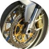
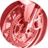
BRAKES INSPECTION GUIDELINES
Vehicle inspection is subjective and the guidelines open to varying interpretation from inspector to inspector. Below is a list of reasons for possible rejection
pertaining to the Braking System for the issuing of a Queensland Department of Transport and Main Roads safety certificate (formerly roadworthy certificate or RWC).
SECTION 8 - BRAKES
Objective: To ensure that the brakes operate effectively and are correctly adjusted.
In this section:-
Brake components, for an air or vacuum brake system, includes all components such as any air lines, hoses, compressors, pumps, valves, chambers, switch
controls, actuators and any associated componentry.
Brake linings includes disc brake pads, shoe linings as well as any separate park brake linings.
Brake pedal includes a brake level as well as any components associated with the pedal or lever.
Hand brake component includes a handle, pedal, actuator (i.e. an electric solenoid) or associated component of a hand brake or park brake system.
Hydraulic component include all parts of a hydraulic system such as the master cylinders and wheel cylinders/calipers.
Warning device includes a failure indicator.
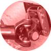
8.1 BRAKE SYSTEM
Possible reasons for inspection rejection:
- Where visible, any brake component is leaking or is not securely mounted.
- Any braking cables are broken, frayed, damaged or not secured.
- Any brake component is seized, severely corroded or inoperative or, where worn, is worn beyond manufacturer's limits.
- Brake chambers (including chamber clamps) or camshaft support brackets are missing, loose, damaged or broken.
- Brake shoes, springs, anchor pins, cam rollers or bushes, pull or push rods, clevis pins, retainers or brake chamber mounting bolts are
missing, loose, damaged or broken.
- Motorbikes do not have two independent braking systems or a single brake that acts directly on all wheels of the vehicle and is
arranged so that effective braking remains on at least one wheel if any part of the system fails.
- Any wiring for electric brakes is disconnected, frayed or insecure.
- A trailer interconnecting flexible hose and/or coupling is not properly secured or damaged.
8.2 BRAKE SYSTEM OPERATION
Possible reasons for inspection rejection:
- The brake controls, when operated, do not cause the corresponding brake to operate (with the engine running, if necessary).
- Any warning device or pressure/vacuum gauge does not operate correctly.
- The motor vehicle's brake test results do not meet the specified stopping distance requirements. (See Note 1)
- Any brake component is broken, excessively worn, leaking, contaminated or is not securely mounted.
- Linkages are not complete and/or components are unduly worn.
- Rods and cables are repaired by welding or joining.
- The brake controls of the towing unit, when operated, do not cause the corresponding trailer brake to operate (with the engine of the
towing unit running, if necessary).
- Trailers with a Gross Trailer Mass (GTM) in excess of 0.75 tonne but not exceeding 2.0 tonnes, are not equipped with a braking system
which operates on at least half the number of axles (Override or electric are acceptable). (See Notes 7 and 8)
- Trailers exceeding 2.0 tonnes GTM are not equipped with brakes which operate on all wheels. (See Notes 7 and 8)
- Brakes fitted to trailers exceeding 2.0 tonnes GTM are not equipped with an effective breakaway system.
- Trailers fitted with double line braking systems do not automatically apply and remain applied for at least 15 minutes after the
control and supply lines are disconnected from the towing vehicle.
- Operation of the service brake of the tow vehicle does not result in operation of the trailer brake.
- Any trailer having brakes which are air or vacuum assisted is not fitted with a reservoir that is protected by a check valve.
- With any brake fully applied, any stroke indicator runs out of travel or indicates that adjustment is necessary.
- Brake chamber push rods move more than 50% of their maximum stroke or travel over centre with the brakes fully applied.
- Brake adjusters are not properly adjusted, are bent, damaged or excessively worn.
8.3 TESTING OF TRAILER BRAKES
Possible reasons for inspection rejection:
- The brake/s do not retard the movement of the trailer.
8.4 BRAKE PEDAL/LEVER CONDITION
Possible reasons for inspection rejection:
- A brake pedal does not have an effective anti-slip surface.
- On rubber faced brake pedals, any metal is showing.
- The brake pedal is bent, damaged, broken or misaligned (outside scope of manufacturer's original design).
- The brake pedal is not secure, not correctly adjusted, binds or is worn so as to affect efficient operation.
8.5 PEDAL TRAVEL
Possible reasons for inspection rejection:
- Maximum brake pressure is not achieved with one application of the brake pedal/lever and is not at least 50% of the maximum travel or
in accordance with the individual vehicle manufacturer's specifications.
- The brake pedal does not remain firm in accordance with the vehicle manufacturer's specifications when light foot pressure is
maintained in the applied direction.
- There is an indication of air in the hydraulic system.
- A brake pedal/lever does not have free travel in accordance with the vehicle manufacturer's specifications.
- When not in use, the brake pedal/lever does not return to the fully released position.
8.6 HAND/PARK BRAKE AND CONTROL LEVERS
Possible reasons for inspection rejection:
- Linkages are not complete or parts are unduly worn.
- Cables are frayed, damaged or restricted.
- Rods and cables are repaired by welding or joining.
- The brake does not fully release when the release control is operated.
- Any hand brake component is not fitted with a locking device capable of holding in any position.
- Any hand brake component is damaged, bent, broken, restricted, missing, not secure or does not allow sufficient application of the
hand/park brake.
- A handle or pedal of a parking/hand brake fitted to a vehicle does not have a reserve of travel of at least one-fifth of the maximum
range of application.
- The control lever does not have a mechanical locking system to enable sustained operation.
- For a motor vehicle built after 1930, the parking/hand brake is not able to hold the vehicle stationary on a gradient of at least
12%.
- The hand/park brake (as applicable to side cars and motortrikes) fails to stop the motorbike being moved and is not able to hold the
motorbike for a period of 5 minutes, facing each way, on a gradient of not less than 30% (as per ADR 33/00).
- Motorcycles fitted with a sidecar, or motortrikes, do not have a hand/park brake fitted. Light Vehicles
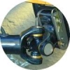
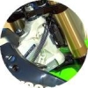
8.7 HYDRAULIC LINES / HOSES
Possible reasons for inspection rejection:
- Hydraulic lines/hoses are not securely mounted, not free from damage or corrosion, show evidence of leakage or are not constructed of
approved material. (See Notes 2 and 6)
8.8 CYLINDERS AND CALIPERS
Possible reasons for inspection rejection:
- Hydraulic components are not secured in a manner as recommended by the manufacturer or are seized, restricted or show evidence of
leakage.
8.9 RESERVOIRS
Possible reasons for inspection rejection:
- Any reservoir is not filled to the manufacturer's recommended minimum level or shows evidence of leakage.
- Any reservoir lid does not seal correctly.
8.10 VACUUM AND AIR COMPONENTS
Possible reasons for inspection rejection:
- Brake components are not secure or operational.
- Any components are frayed, perished, corroded or misaligned, or show evidence of leakage.
- Filter units for air compressors or vacuum pumps are missing, loose, blocked or damaged.
- Vacuum is not available immediately the engine is started.
- After engine shut down, there is not sufficient vacuum reserve to allow for at least one assisted brake application.
- Componentry is not correctly adjusted or free from binding.
8.11 DISCS, PADS, DRUMS AND LININGS
Possible reasons for inspection rejection:
- Brake linings are worn below wear indicators. If no indicators are provided, the thinnest part of the lining is worn below
manufacturer's specifications. (See Notes 3 and 5)
- Drums or disc rotors are worn or machined below manufacturer's specifications. (See Note 4)
- There are substantial cracks on friction surfaces, external cracks or mechanical damage.
- Lining material is contaminated with oil, grease or brake fluid.
NOTES:
[1] Minimum Light vehicle service brake deceleration values from 35km/h
|
Vehicle with a gross vehicle mass Under 2.5 tonne must achieve a deceleration value of at least: |
Vehicle with a gross vehicle mass of at least 2.5 tonne must achieve a deceleration value of at least: |
| Average Value |
3.8m a second a second
(39%g) |
2.8m a second a second
(29%g) |
| Peak Value |
5.8m a second a second
(60%g) |
4.4m a second a second
(45%g) |
In the case of a vehicle that cannot be tested with a decelerometer, the service braking system must stop the motor vehicle from a speed of 35 km/h:
a) within 12.5 metres for a vehicle or combination with a gross mass up to 2.5 tonnes;
b) within 16.5 metres for a vehicle or combination with a gross mass of 2.5 tonnes or over.
Minimum Light vehicle emergency brake deceleration values from 35km/h
|
Vehicle with a gross vehicle mass Under 2.5 tonne must achieve a deceleration value of at least: |
Vehicle with a gross vehicle mass of at least 2.5 tonne must achieve a deceleration value of at least: |
| Average Value |
1.6m a second a second
(16%g) |
1.1m a second a second
(11%g) |
| Peak Value |
1.9m a second a second
(19%g) |
1.5m a second a second
(15%g) |
In the case of a vehicle that cannot be tested with a decelerometer, the emergency braking system must stop the motor vehicle or combination from a speed of
35 km/h:
a) within 30 metres for a vehicle or combination with a gross mass up to 2.5 tonnes;
b) within 40.5 metres for a vehicle or combination with a gross mass in excess of 2.5 tonnes.
Minimum motorbike service brake deceleration values from 35km/h
|
A motorcycle must achieve a deceleration value of at least: |
| Average Value |
3.8m a second a second (39%g) |
| Peak Value |
5.8m a second a second (60%g) |
In the case of a vehicle that cannot be tested with a decelerometer, the emergency braking system must stop the motor vehicle or combination from a speed of
35 km/h:
a) within 12.5 metres for a vehicle or combination with a gross mass up to 2.5 tonnes;
b) within 16.5 metres for a vehicle or combination with a gross mass of 2.5 tonnes or over.
[2] ADR 7/00 - Hydraulic Brake Hoses was repealed as of 18 December 2003 and the requirements for hydraulic brake hoses are now included in ADR 42/04 Section
15 (Brake Tubing and Brake Hose) which states;
Flexible hydraulic brake hoses, air or vacuum brake tubing and air and vacuum hose, flexible and hydraulic power hose between the 'Brake Power Unit 31/00' or 'Brake
Power Unit 35/00' and the master cylinder or its equivalent must conform to SAA, SAE, BS, JIS, DIN, ISO or ECE Standards specified for flexible brake hoses, air brake
tubing or hose or vacuum brake tubing or hose or hydraulic power tubing or hose and be fitted to the vehicle so as to prevent chafing, kinking or other mechanical
damage under normal motion of the parts to which they are attached.
Note: The repealing of the ADR now permits hydraulic brake hoses to comply with the requirements of ADR 42/04. As such, older vehicles can comply with the revised
standard.
Made up hoses are not acceptable. Where brake hoses are replaced with aftermarket products, relevant standards approval marking is required.
Braided hoses are acceptable provided they are approved and correctly marked. Refer to Vehicle Standards Instruction G21 - Information Sheets for Approved Examiners -
Information Sheet No. 7 - Braided Brake Hoses.
[3] Where manufacturer's specifications are not provided, the minimum thickness for bonded linings is 0.8mm or 0.8mm above the head of a rivet.
[4] Where manufacturer's specifications are not provided for drums, scoring must not be more than 1.5mm for light vehicles. Refer to AIS Information Sheet No. 16
- Brake Drums and Discs.
[5] When an approved examiner is inspecting a braking system and components such as pads, linings, discs and drums are not visible, the wheels and drums must be
removed to ensure all parts are in a serviceable condition.
An approved examiner may require the removal of one (1) or more wheels and brake drums or rotors if the examiner has reasonable grounds to believe that a defect
exists.
Where wheels and brake componentry are removed for the purpose of inspection, the proprietor must notify the owner of this requirement and negotiate appropriate labour
costs and charges for non re-useable parts such as lock nuts, lock tabs, split pins, lubricants etc. before proceeding. These additional charges are not part of the
examination fee.
[6] Normal commercial copper tubing has been prohibited from use in brake systems because it is considered prone to cracking due to work hardening. However,
there is a Society of Automotive Engineers (SAE) Recommended Practice called Tubing - Motor Vehicle Brake Tubing Hydraulic - SAE J1047 which is the accepted industry
standard.
Persons wishing to use copper tube for vehicle hydraulic brake lines must first provide proof of compliance with SAE J1047 or equivalent standard.
[7] Aggregate Trailer Mass (ATM) is the total mass of the laden trailer when carrying the maximum load recommended by the manufacturer. This includes any mass
imposed onto the drawing vehicle when the combination vehicle is resting on a horizontal supporting plane.
Gross Trailer Mass (GTM) is the mass transmitted to the ground by the axle or axles of the trailer when coupled to a drawing vehicle and carrying its maximum load
approximately uniformly.
[8] Brake testing of trailers fitted with override brakes
Where possible, testing of any override brake system should be undertaken by compressing the brake actuating device and attempting to move the trailer. This can only
be undertaken where a parking brake is fitted to the trailer. In accordance with the ADRs, most trailers with override brakes are not required to be fitted with a
parking brake. However, a suitable device can usually be easily incorporated into the actuating mechanism and is highly recommended for improving safety when the
trailer is uncoupled from the towing vehicle.
Brake testing of trailers fitted with brakes other than override brakes
With the trailer attached to the towing vehicle, apply the trailer service brake and attempt to move the trailer forward.
Testing of the park brake, where fitted
Apply the parking brake and attempt to move the trailer. The trailer may be coupled to the towing vehicle for the test but it should be ensured that the transmission
is in neutral and the brakes are off.
If you require further information about safety certificate inspections or inspection guidelines phone
Brian Harper
at
MOTORCYCLE ROADWORTHYS
on
1800 BIKE RWC
1800 245 359
or
0402 544 115
WE ACCEPT

|