Queensland Department of Transport and Main Roads introduced the safety certificate in November 1999 to replace the old roadworthy certificate or RWC, and it became
mandatory to obtain and display a current safety certificate on any registered motorcycle from the moment it's offered for sale.
The only times it's not required to display current safety certificate on a motorcycle for sale is when the motorcycle's either unregistered or is traded to or
between licensed motor dealers.
Queensland Department of Transport and Main Roads safety certificates can only be issued by Approved Inspection Stations (AIS), being service stations, garages or
workshops approved by Queensland Department of Transport and Main Roads to conduct inspections.
For private motorcycle sellers, Queensland Department of Transport and Main Roads safety certificates must be issued in the two months or 2000 kilometres prior to
sale, whichever comes first.
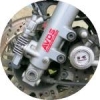
You are required to display a safety certificate in a conspicuous place and for motorcycles it's either on the forks or front guard.
Failure to display a Queensland Department of Transport and Main Roads safety certificate on the motorcycle from the time it's first offered for sale can carry an
on-the-spot fine penalty of $550.
Information on this website relating to motorcycle inspection is drawn from the Queensland Department of Transport and Main Roads Code of Practice for Approved
Inspection Stations (AIS) and Approved Persons; guidelines followed during safety certificate inspections and vehicle modification certification.
Following the code of practice guidelines below and rectifying faults you uncover should assure your motorcycle will pass on first inspection, avoiding any inconvenient
and possible costly re-inspection.
Vehicle inspection is subjective and the guidelines open to varying interpretation from inspector to inspector. Below is a list of reasons for possible rejection
pertaining to the Steering and Suspension for the issuing of a Queensland Department of Transport and Main Roads safety certificate (formerly roadworthy certificate or
RWC).
SECTION 6 - STEERING AND SUSPENSION
Objective: To ensure that the steering and suspension is in good working order and allows the driver effective control of the vehicle.
In this section:-
Control devices, in relation to an L-Group vehicle, includes knobs levers.
Axle locating devices include locating arms and associated componentry.
Sway bar components include sway bars, linkages and bushes.
Suspension dampening components means any part of the vehicle's suspension dampening system and includes shock absorbers and suspension struts.
6.1 STEERING COMPONENTS
Possible reasons for inspection rejection:
- Any steering components are not in good condition, are missing, cracked or broken or are not securely mounted and free from damage or
distortion or have free play beyond manufacturer's limits. (See Note 1)
- Steering stops do not prevent wheels or tyres from fouling any component on full steering lock.
- Any fastener is missing or insecure.
- Steering components are removed, heated, welded (modified) or bent without approval.
- The steering wheel is not located to the right hand side of the vehicle unless the vehicle is 30 years or older.
- Any power steering component (electric or hydraulic) is leaking, not secure, damaged or inoperative.
- Any power steering belts are loose, broken, frayed, missing or cracked through to reinforcing plies.
- The steering system is not designed to transmit energy by mechanical means only (power assisted steering systems are acceptable).
- Free play in any component exceeds the manufacturer's specifications. Where the manufacturer does not provide specifications or they
are no longer appropriate, the free movement exceeds 3mm.
6.2 STEERING FREEPLAY
Possible reasons for inspection rejection:
- With the road wheels in the straight ahead position, and the engine running (if the vehicle has power steering), freeplay in the
steering wheel rim outer edge exceeds 75mm in steering wheels up to and including 450mm diameter or 100mm for steering wheels over 450mm diameter.
6.3 STEERING WHEEL
Possible reasons for inspection rejection:
- Steering wheel is not securely fixed to the steering column mast shaft or is not free from structural damage (e.g. loose or damaged
padding).
- The steering wheel and accessories (padded hubs, covers, steering wheel grip etc.) are loose or have deteriorated to an extent that
they are likely to cause injury to the occupant.
- Steering wheel does not meet the minimum diameter requirements. (See note 2)
- Steering wheels fitted to light passenger vehicles manufactured on or after 1 January 1971 are not replaced by a steering wheel which
complies with ADR 10A or, where ADR 69 applies, the steering wheel is not of the same specification as the one provided by the vehicle manufacturer. (See Note
2)
6.4 STEERING SHAFT
Possible reasons for inspection rejection:
- The steering shaft is not secured to the steering box worm shaft, pinion or coupling or is incorrectly aligned or adjusted.
- Where a coupling is fitted, it is loose, frayed or otherwise damaged.
6.5 OUTER COLUMN
Possible reasons for inspection rejection:
- The outer column is not securely mounted or free from cracks and damage. (See note 3)
- Wear in the bushes/bearings supporting the shaft exceeds manufacturer's tolerances.
- Where ADR 25 applies, the ignition key can be removed in any position except in the locked position.
- When engaged, the anti-theft lock does not prevent at least one of the following actions:
- Steering of the vehicle;
- Engaging the forward drive gears;
- Release of the brakes.
6.6 STEERING BOX/RACK
Possible reasons for inspection rejection:
- Any manual or power steering component is not securely mounted or free from excessive side or end play, displays roughness when
operated, binding or leaks oil when operated through its normal range of travel.
- Steering rack seals are damaged, deteriorated or missing.
6.7 STEERING LINKAGES MECHANISM
Possible reasons for inspection rejection:
- With the wheels off the ground, the steered road wheels do not turn freely to the left and right through their normal full range of
travel.
- Steering linkages are damaged, worn, misaligned or are not correctly located or fitted.
- Tie rod and drag link ends are not secured in both the rod and taper with fasteners that are suitably locked (e.g. split pins,
lockwire, tabs or self locking nuts).
- Free play due to wear in any component exceeds the manufacturer's specifications. Where the manufacturer does not provide
specifications or they are no longer appropriate, the free movement exceeds 3mm.
- Steering idler or bushing is loose on mountings or is worn in excess of manufacturer's specifications. Where the manufacturer does not
provide specifications or they are no longer appropriate, the free movement at the end of the idler arm or idler pivot axis exceeds 8mm.
- Through the full range of steering movement, steering stops do not prevent wheels or tyres from fouling the vehicle chassis or
suspension components on full lock.
6.8 ARMS AND LINKAGES
Possible reasons for inspection rejection:
- There is any movement in the spline between the pitman arm and the steering box or between any thread or tapered joint.
- The free movement measured at the front or rear of the tyre when attempting to turn the assembly from the right to left with the
vehicle supported on the lower control arm exceeds the manufacturer's specifications. Where the manufacturer does not provide specifications or they are no longer
appropriate, the free movement exceeds the following measurements:
- Wheel rims 405mm or less - 7mm;
- Wheel rims over 405mm up to 455mm - 10mm;
- Wheel rims over 455mm - 13mm.
- The looseness at any one point is responsible for half or more of the movement specified in the above table.
6.9 STEERING MECHANISM AND DESIGN
Possible reasons for inspection rejection:
- The handlebar of a motorbike is not secure or free play in the steering head exceeds manufacturer's specifications.
- Where steering linkages are fitted, any rotational free play exceeds 10mm at the end of the handlebar.
- Steering gear is not so designed so as to eliminate accidental detachment or overlocking.
- Steering components are misaligned with the frame or are damaged, fatigued, corroded or distorted.
- Operation of the handlebar is not smooth (without jamming, fouling or roughness in its operation) from "lock to lock".
- Any equipment fitted to the motorbike, including motor tricycle(s) and side car, prevents free movement (e.g. the handlebar must not
come into contact with the fuel tank).
- The handlebar assembly is not constructed of suitable material, adequately mounted or free of sharp edges and protrusions.
- The handlebar is not symmetrical on either side of the front wheel and steering head assembly.
- The handlebar is not of the same shape and length on both sides of the front wheel and steering head assembly.
- If the forks are raked (i.e. modified wheelbase), the horizontal distance between the mid-point of the steering yoke bearings and a
point vertically above the centre of the front wheel exceeds 550mm.
- Motorbikes fitted with offset triple clamps have a trail measurement of less than 75mm. (See Note 7)
- Handlebar grips and control devices have deteriorated to an extent that they are not secure, or are excessively damaged or unduly
worn.
6.10 HANDLEBAR DIMENSIONS
Possible reasons for inspection rejection:
- The distance between the extreme ends of the handlebar assembly is greater than 900mm or less than 500mm.
- For motorbikes manufactured prior to July 1988 the lowest part of the handgrip on the handlebars is higher than 380mm above the
steering yoke. (Handlebars modified in accordance with the LM section of the National Code of Practice for Light Vehicle Construction and Modification should meet
these requirements).
For motorbikes manufactured from 1 July 1988 the height of the lowest part of the handgrip is more than 380mm above the lowest part of the upper surface of the
rider's seat.
6.11 SUSPENSION COMPONENTS
Possible reasons for inspection rejection:
- Components are distorted, cracked, corroded, fractured or are worn beyond manufacturer's specifications.
- Free play in any component exceeds the manufacturer's specifications. Where the manufacturer does not provide specifications or they
are no longer appropriate, the free movement exceeds 3mm.
- Link ends are not secured with suitably locked fasteners (e.g. split pins, lockwire, tabs or self locking nuts).
- Any fastener is missing or not secure.
- Suspension components are worn beyond manufacturer's specifications.
- Suspension components are not securely mounted and aligned, or are missing bent or are repaired or modified by heating or welding
without departmental approval. (See Note 8)
6.12 SPRING MEDIA COMPONENT i.e. springs, spring hangers, torsion bars
Possible reasons for inspection rejection:
- Components including the axle, "U" bolts, spring hangers, centre bolts etc. are not correctly aligned, adjusted, securely mounted or
are missing, unduly worn, rusted, cracked or damaged.
- Nuts do not fully engage "U" bolts.
- Suspension heights are lowered or raised by more than one-third of the manufacturer's bump stop clearance. (See Note 6)
- Any spring is cracked, broken, missing or displaced by more than 10% of its width or makes contact with wheels, brakes or the
frame.
- Non-standard or manufacturer's non-optional air or hydraulic suspension is fitted without specific departmental approval. (See Note
4)
- Air bag or hydraulic suspension components (if fitted) are not in working condition or are leaking or perished.
- Coil springs do not remain in locating seats on full suspension droop.
- If a vehicle body (front or rear) is lowered or raised, the following reasons for rejection are based on the manufacturer's dimensions
for the standard unmodified vehicle while unladen:
- The ride height measured between the rubber bump stop and the corresponding metal stop is reduced by more than one third.
- The rebound travel measured between the rubber rebound stop and the corresponding metal stop (or the extension of the shock
absorber for vehicles without a rebound stop) is reduced by more than one third.
- Mandatory lighting/lamp heights no longer comply.
- The normal relationship between the front and rear suspension heights is unduly affected.
- Suspension coil springs are lowered by cutting or heating.
- Leaf spring suspension is altered by the use of adjustable metal plates or by placing the leaf springs to the opposite side of the axle
(repositioning over axle spring location to under axle spring location or vice versa).
- Lowering blocks that are made of material other than either steel or aluminium.
6.13 AXLE LOCATING ARMS AND DEVICES i.e. shackles and bushes
Possible reasons for inspection rejection:
- Axle locating devices are not in good working order, are excessively worn, cracked or damaged, or are not securely mounted or correctly
adjusted.
- Extended or non-approved shackle plates are fitted except where approved by the vehicle manufacturer as an option.
- Any free movement in pivot pins, king pins, ball joints, bushes or trunnions, when measured at the outer extremities of the tyres,
exceeds manufacturer's tolerances, or where manufacturer's tolerances are not available, exceed the following:
- Wheel rims 405mm or less - 7mm;
- Wheel rims over 405mm up to 455mm - 10mm;
- Wheel rims over 455mm - 13mm.
6.14 SWAY BARS, LINKAGES AND BUSHES
Possible reasons for inspection rejection:
- Sway bar components are broken, loose, unduly worn, disconnected or have been removed.
6.15 WHEEL BEARINGS
Possible reasons for inspection rejection:
- Any wheel bearing is incorrectly adjusted, rough, noisy, loose on stub axle, does not rotate freely or is leaking.
- Movement between disc brake rotor/brake drum and backing plate exceeds manufacturer's specifications.
6.16 SUSPENSION DAMPENING SYSTEM
Possible reasons for inspection rejection:
- Suspension dampening components are not fitted, are inoperative, not securely mounted or brackets or rubbers are missing, worn or
damaged.
- Suspension dampening components do not effectively dampen movement or show signs of leakage. (See Note 5)
6.17 GROUND CLEARANCE
Possible reasons for inspection rejection:
- The road clearance of a fully laden vehicle is less than 100mm measured at any part of the vehicle other than the wheel rim or brake
backing plates. If a lesser clearance has been specified by the manufacturer, the clearance must not be less than that specified clearance. (See Note 6)
Notes about Section 6 (Steering and suspension):
[1] Must be inspected through the full range of steering movement, steering stops must prevent wheels or tyres from fouling the vehicle chassis or suspension
components on full lock.
[2] The minimum diameter of any replacement steering wheel must not be less than 330mm. The replacement wheel must be designed in a similar manner to the original
(e.g. padded centre hub and dished spokes).
A replacement steering wheel fitted to a vehicle complying with ADRs 69/.. or 73/.. must remain compliant.
A replacement steering wheel fitted to a pre ADR 69/.. vehicle equipped with a driver's side airbag as original equipment must remain fitted with an airbag operating
to manufacturer's specifications.
[3] Special attention should be made to the collapsible section (if applicable) of the outer housing.
[4] Airbag or air pressurised shock absorber helper springs may be fitted in addition to the original suspension without specific departmental approval.
[5] Shock absorbers or suspension struts are permitted to show signs of oil weeping provided the units still function as required. Check with component manufacturer
for full details.
[6] Ground clearance requirements for motor vehicles are detailed in Vehicle Standards Instruction G21 - Information Sheets for Approved Examiners - Information Sheet
No. 13.
[7] If offset triple clamps are fitted to the front fork assembly (i.e. the clamps are machined such that the angle of the fork stanchions is at an angle to the
steering head axis), then the trail measurement should be checked to ensure that the centre of the front axle is at least 75mm behind the point where the steering head
axis line intersects the ground.
[8] It is common industry practice to repair or re-manufacture spring hangers (rocker boxes). This will necessitate the welding of the original castings (in the case
of repairing) to rebuild the component to its original configuration. This means of repair is acceptable, provided the method of repair and welding technique is to an
acceptable standard. This method of repair is acceptable for trailers only.


